|
This page explains the capabilities the studio offers to edit a BPEL process. |
Introducing the BPEL Designer
The BPEL Designer embedded in the studio is a modified version of the official Eclipse BPEL Designer.
The layout is a little bit different, and some internal mechanisms were changed too.
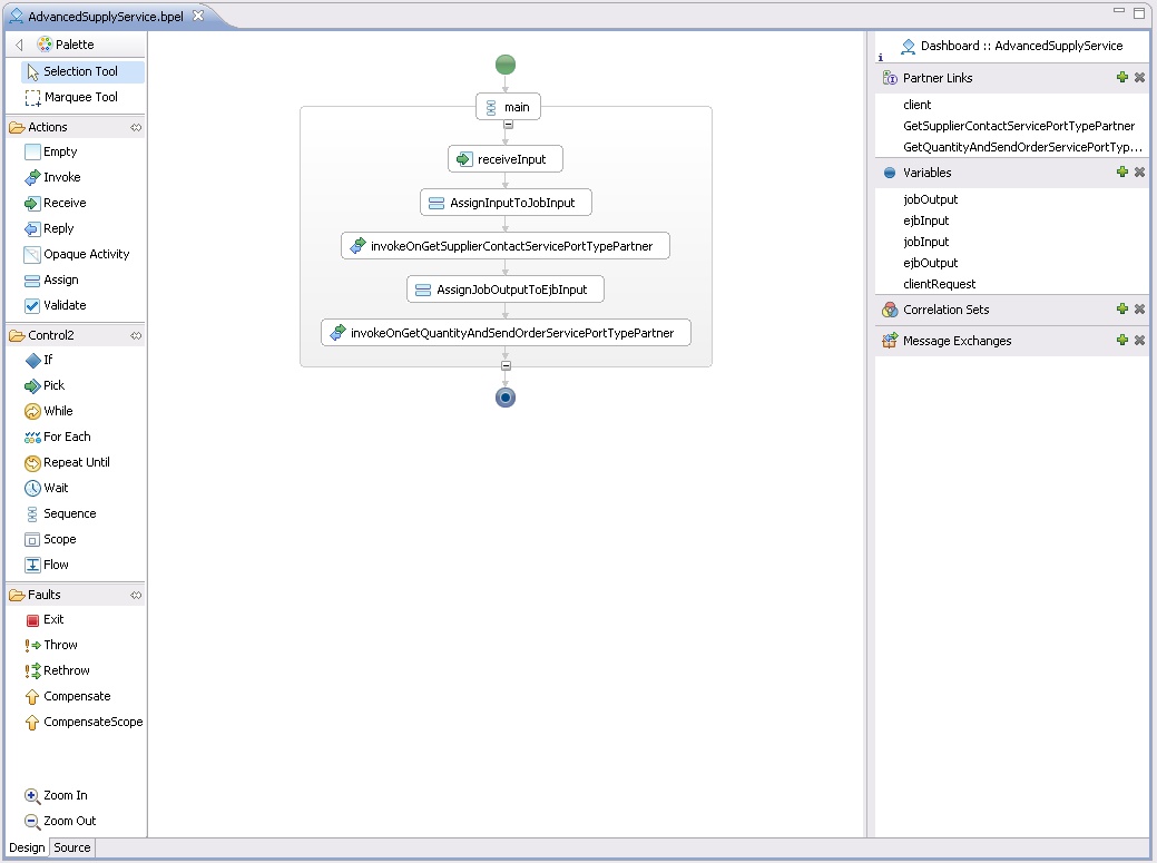
The designer is made up of two tabs: one displays a graphical view of the process, while the second one shows the source code of the BPEL.
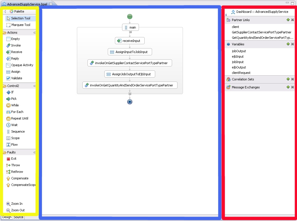
The graphical tab is divided into three parts:
- The palette can be used to select activities to insert on the diagram, or to change UI settings (e.g. the zoom or the mouse icon).
- The diagram area is the main area and shows the processing flows.
- The dashboard lists non-visual elements of the BPEL process, such as variables and partner links (the BPEL Designer does not make them visible in the diagram itself).
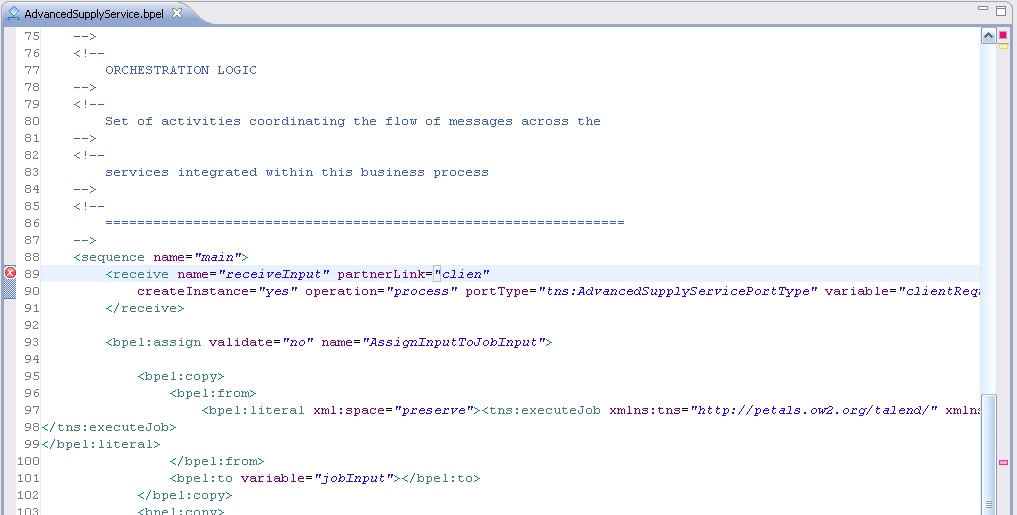
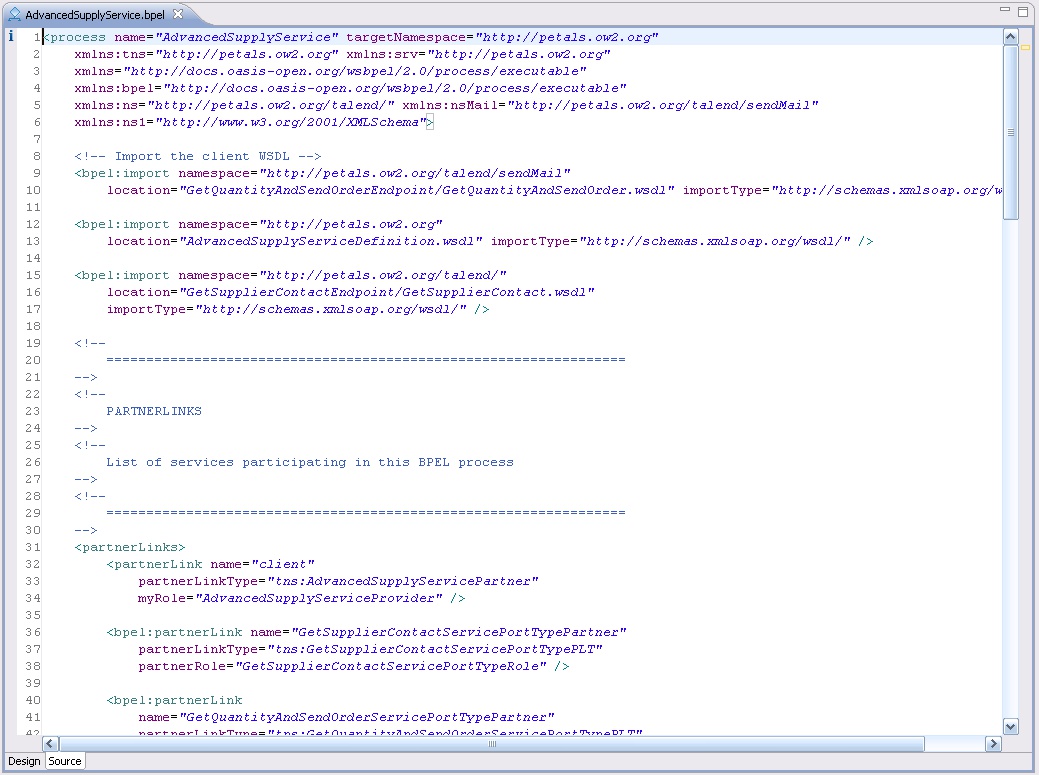
The source tab uses the Eclipse XML editor.
BPEL XML schemas have been registered in the XML catalog, so that contextual help (Ctrl + L) can propose mark-ups and attributes to insert.
Adding activites in the process
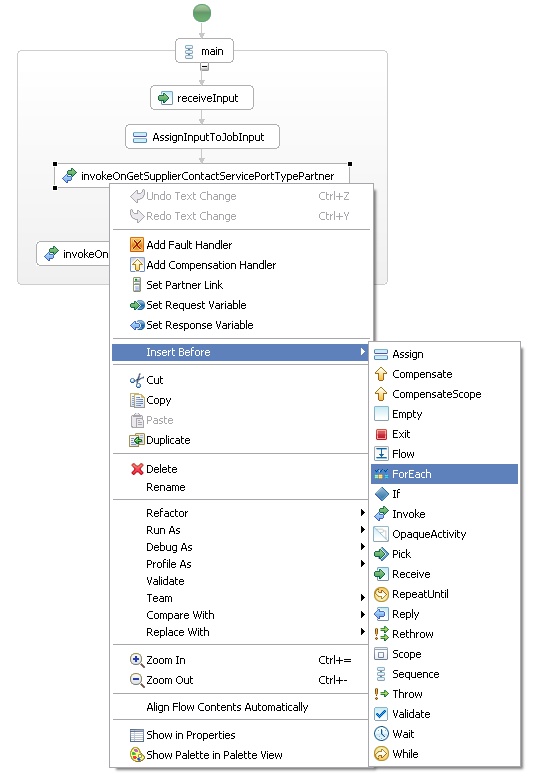
Activities can be added on the diagram by 2 means:
- You can either select an activity in the palette (by clicking it), and then clicking your diagram at the location where this activity should be added.
- Or, you can right-click a diagram element and use the Add or Insert Before actions.
Creating a new partner link
A partner link represents a service to invoke. It is associated with a PortType (a WSDL interface) and with roles in the process.
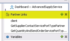
To create a partner link, click the "+" symbol located next to the Partner Links category in the dashboard.
Give the new partner link a name. A convention may be taking the port type (interface) name and suffixed by the word "Partner".
Now, import the WSDL of the service to invoke in the project.
You can either try a manual copy, or use the import wizard available in the studio.
Because WSDL definitions may draw several file dependencies, it is better to create a sub-directory to place the imported files.
This WSDL must be the definition of the service to invoke. It will be associated with the new partner link.
Then, go in the Properties view, under the Details tab.
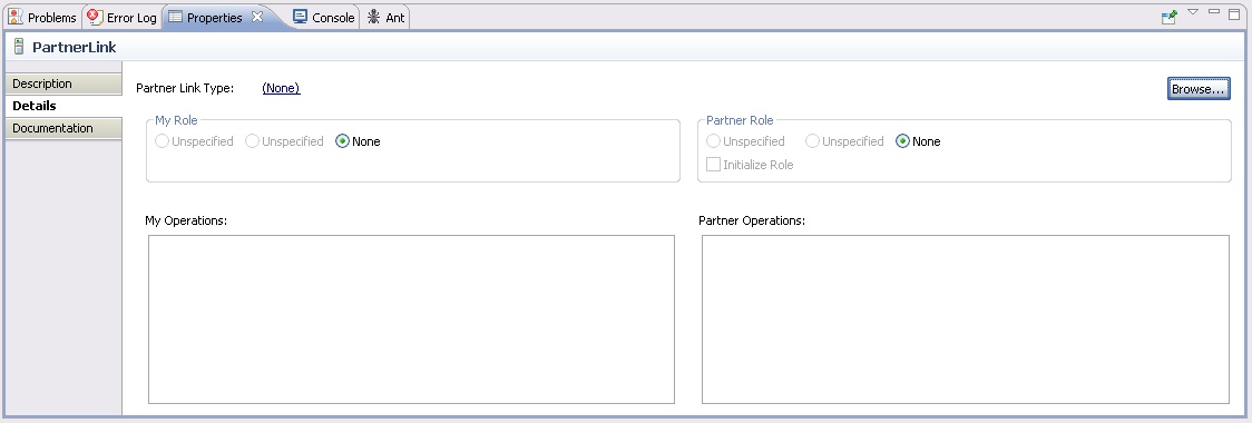
Click Browse.... A dialog shows up.
It shows available port types. If the one you target is not there, click Add WSDL.
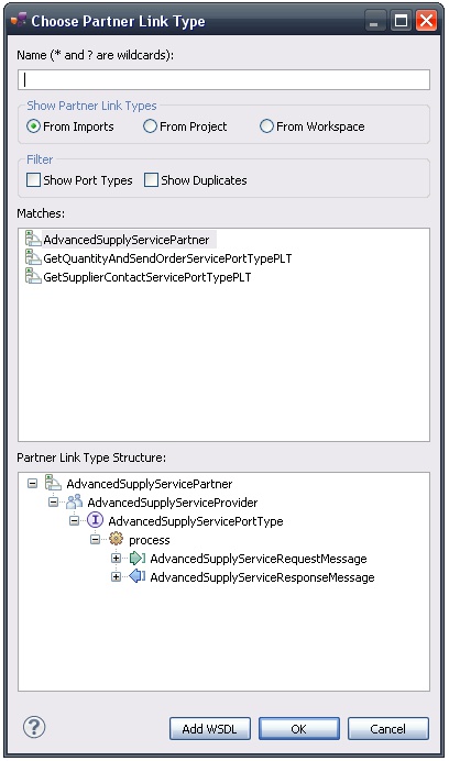
Another dialog shows up. Use it to select the WSDL you imported in your project.
Be careful if you take a WSDL located outside the project. Imports may be expressed through a relative URL.
Once you have picked up a WSDL, click OK. At least one new port type should have appeared in the first dialog.
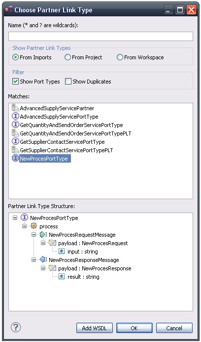
Select this new port type and click OK.
A wizard opens up and asks for the properties of the partner link.
The first page asks for the name of the partner link type. Generally, it is the port type name, followed by "PT".
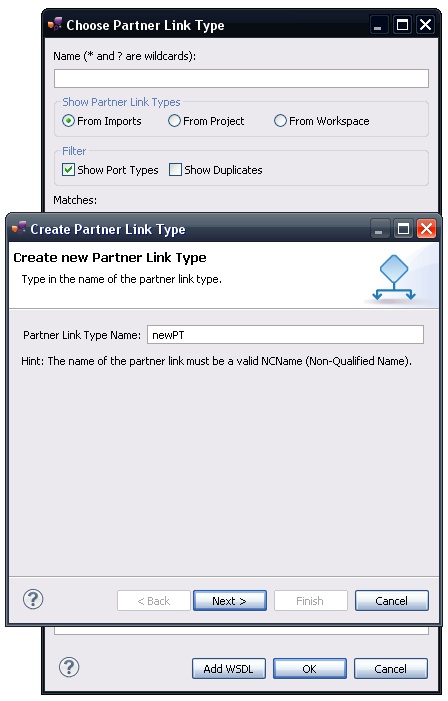
Click Next.
On the next page, select the port type to use, and type in a role name for the partner link.
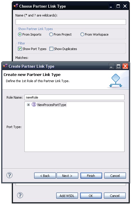
Click Next if you want to define a second role, or Finish if one is enough.
This action closes all the dialogs.
Sometimes, there can be another one about name space mapping. It simply asks for a prefix to associate with a namespace.
Before saving your file, set the MyRole and PartnerRole in the properties.

Save your file to be sure there is no error.
Invoking a service
Invoking a service in BPEL is achieved by inserting an Invoke activity in the process.
Before creating an Invoke activity, you need to have a partner link.
To create the invocation, create a new Invoke activity.
Give the invocation a name (generally, invoke<partner link name>) and go into the Properties view of this activity.
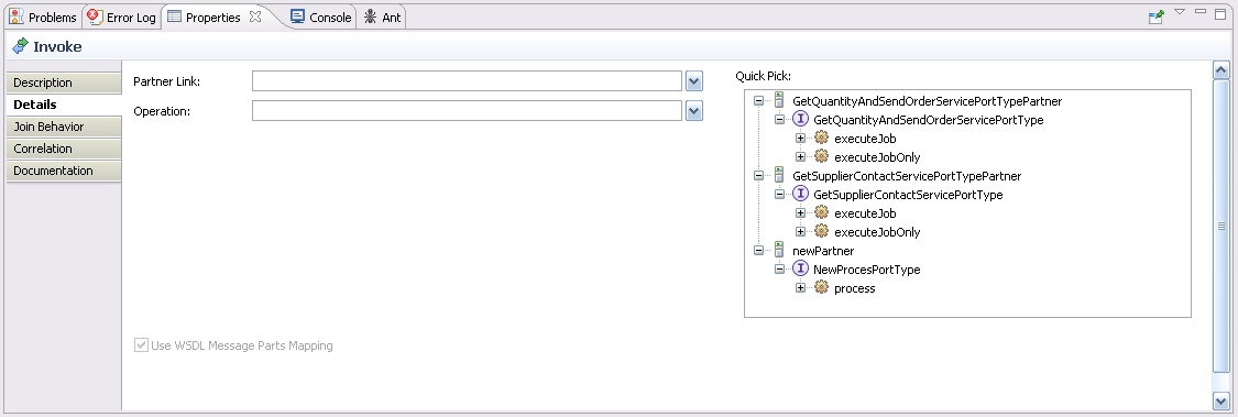
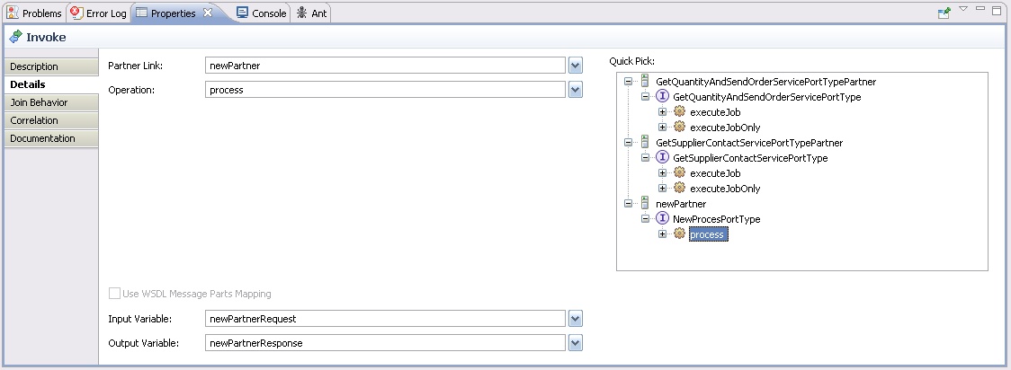
An invocation needs the following elements:
- The partner link to invoke (a partner link is identified by a qualified name).
- The operation to invoke (also identified by a qualified name, as described in the WSDL of the partner link).
- An input variable: which XML message will be sent to the partner link?
- Optionally, an output variable. It depends on the message exchange pattern (is the operation supposed to return something?).
The output variable is used to store the response of the partner link.
You can fill in these fields through the properties.
Or, you can also use the Quick Pick box, on the right.
Select an operation: all the fields will be filled-in automatically and the required variables will be created when necessary.
Save your file to be sure there is no error.
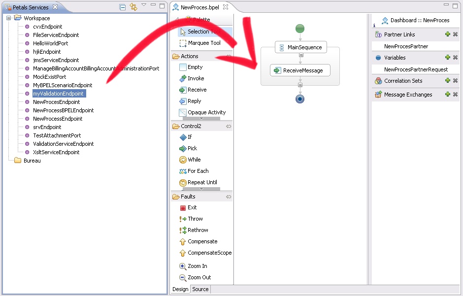
Shortcut to create Petals invocations
Creating an invocation for a Petals service can be achieved as explained above, by using the features of the BPEL Designer.
However, there is an alternative solution for Petals services.
It consists in using a drag'n'drop from the Petals Services view onto the BPEL diagram.
It will:
- Create a partner link (if one does not already exist with this name) and a partner role.
- Create an invocation activity at the drop location.
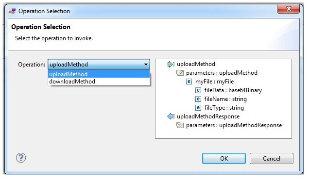
- Ask the operation of this service to invoke.
- Create the input (and if required, the output) variable(s) to use in the invocation properties. The variable types are initialized.
- Import the partner's WSDL definition in the BPEL project.
Making assignations
Assignations are BPEL activities to assign elements and attribute values from one variable to another one.
They are created like any other activity.
Then, go in the Properties view, in the Details section.
Assignations are in fact a sequence of field-to-field assignations.
Affecting the value of one element/attribute to another one is one step of the sequence.
There are are many steps as required to have the variable's content complete.
Here is an example of assignation.
First, the variable to assign is initialized with a XML content that matches its XML type.
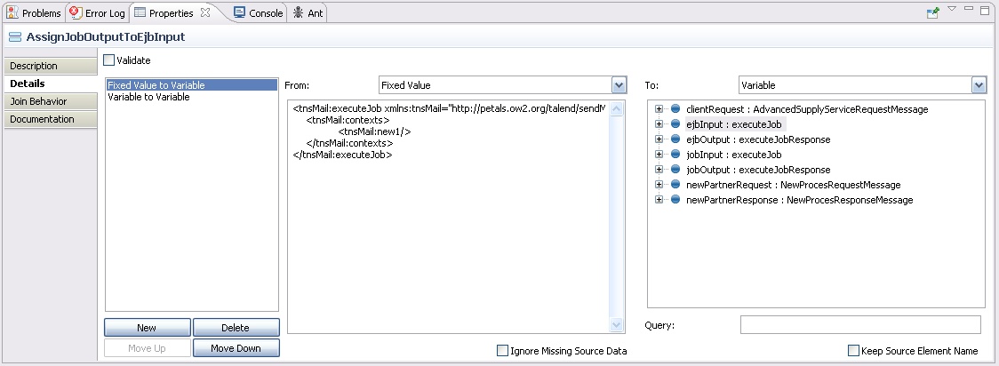
And then, an element value from a previous variable is copied into an element of the variable to assign.
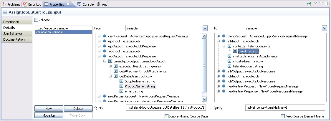
| To ensure the portability of your BPEL process, and to avoid issues at runtime, you should always initialize your variables. This is in particular true for optional elements, that cannot always be created automatically. |
Validating the process
BPEL files that are contained in Service-Unit projects and in BPEL croquis are automatically validated on every modification.
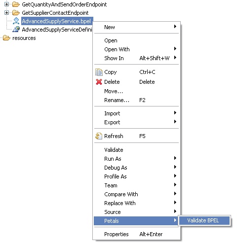
It is also possible to explictely validate a BPEL file by right-clicking it and selecting Petals > Validate BPEL.
Note that this validation is based on the same validation mechanism than the Petals BPEL engine.
There are additional validation rules than in the usual BPEL Designer.
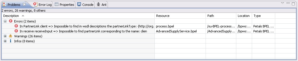
Errors and warnings are visible in the Problems view...
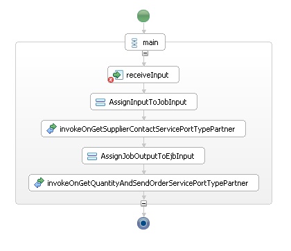
... on the diagram...
... and in the source view.